
Disclaimer and Warning: the following information on steering system modification is meant as an explanation of what we did, not as instructions for any work on any other vehicle. USE AT YOUR OWN RISK. Any steering system work done on any vehicle should be carried out only by qualified steering and suspension technicians using the highest established standards of work and the best quality new parts.
There are many ways to upgrade the Ross steering on a Willys station wagon. Some modifications use a Ford steering box mounted behind the main front cross member, others use a completely Hydraulic steering control (using a hydraulic ram instead of a steering box), but the most well known modification uses the famous GM designed Saginaw steering box mounted ahead of the front cross member. Newer CJs and TJs all use Saginaw steering boxes, therefore this seemed like the most appropriate conversion to pursue.
Many conversions use 4 bolt 1960s vintage Saginaw boxes having “76” embossed on the casting (series 800 boxes), apparently found in Camaros. We were worried this this type of box would be much too fast for our old Willys wagon, so we chose a 3 bolt 1980 Cherokee Saginaw box expecting it to have a slower and safer 4+ turns lock to lock ratio (the original Ross steering box ratio was 4.25 turns lock to lock). As it turned out, the Cherokee steering box ratio also gave about 2-2/3 turns lock to lock. This much faster ratio, coupled with the effortless power assist shows up the severe limitations of the suspension every time you drive old Bluebell. I’m sure it would be very easy for an inexperienced driver to turn her over if care is not taken to drive sedately and smoothly.
Step One July 2006
Steering column installation
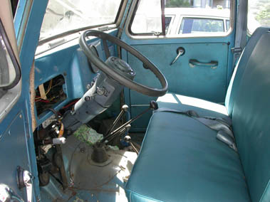
- 1985 Cherokee tilt steering column (actually a GM column) allows old-fashioned upright steering wheel angle
- Column looks presentable and matches reupholstered front seats and 1995 Dodge Caravan seat belts all in blue
- Connecting the Cherokee turn signals and horn to the Willys wiring harness was difficult as we had to figure out the function of each wire ourselves from scratch
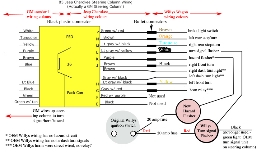
There were several wiring harnesses on the Cherokee column – all were removed except the harness above. We were unable to locate a wiring diagram anywhere and both Jeep and GM dealership parts departments and service managers could not help either. We figured out the wiring, with the help of a ‘light truck’ GM wiring diagram library reference book by a process of elimination. We used all the Cherokee wires except ‘F’ (red with purple) and ‘E’ (black) and connected them to the original Willys wiring. Once again, this work took time and patience.
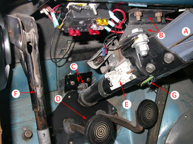
New Column placement and support
- Cherokee column(A) attaches to the Willys dash using a simple ‘double angle iron’ upper support(B). Old rusty bolts will be replaced!
- Lower support(C) uses a modified Wagoneer clamp and plate bolted through the fire wall
- D is the position where the original column passed through the pedal plate. We decided to keep an older style upright angle to the new column but not quite as upright as the original
- E is the currently disused Cherokee high-beam switch (what could it be used for in future?). The original high-beam switch on the floor works fine
- F is the Orscheln lever for the drum-brake at the end of the transfer case
- G is a peek at the GM wiring for turn-signal/brake/hazard & horn
Step Two
Saginaw steering box attachment.
Bracketry ended up in two pieces which allows a small amount of flexibility. Grade 8 hardware was used throughout.
- Right…thick walled tubing welded together is similar to the steering box support casting found in many jeeps.
- Middle…thick (1/2″, 3/8″ & 1/4″) steel plate pieces were welded to make a strong triangular support unit for the Saginaw box. The lower gusset, bolted to the winch front crossmember, distributes forces over both chassis rails.
- No new holes were drilled into the chassis rails. Nothing was welded to the vehicle frame either – it can all be removed…
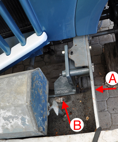
Here you can see the bracket in place ready to receive the steering box. Note that the 1/2″ thick vertical plate through which the attachment bolts secure the box, ‘stands proud’ of the chassis rail (and is not welded to it). This positions the new steering box laterally so that the original drag link can be used. (We had to shorten the draglink about 1 inch)
The winch-supporting arms (A) are 3/8″ thick and act to strengthen the chassis rail – this makes for a very strong set up. If we did not have a winch cradle, we would have made a new front crossmember to function the same way.
A recess (with drainage hole B) was let into the lower winch cradle so as to not interfere with the front of the steering box.
Finally, time for box bolt up!
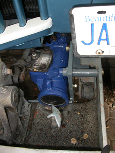
- 3 bolt Saginaw (metric O-ring hose end) power steering box finally snuggles on frame behind winch cradle. I was told the source of the steering box was a 1980 Jeep Cherokee – it leaked slowly for years and can be seen here freshly rebuilt (summer 2009).
- Box is angled upward at 7 degrees
- Lower rad support/grill area had to be trimmed to allow hose clearance
To see a step by step rebuild of this Saginaw steering box go to the Saginaw steering box rebuild page.
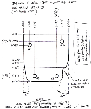
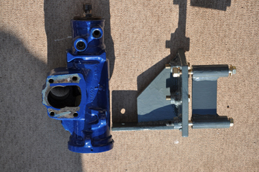
Here is the main attachment bracket for the Saginaw steering boxes.
The same bracket works for manual boxes, three and four bolt powere boxes
Step Three
Custom Saginaw pump installation – a challenge!
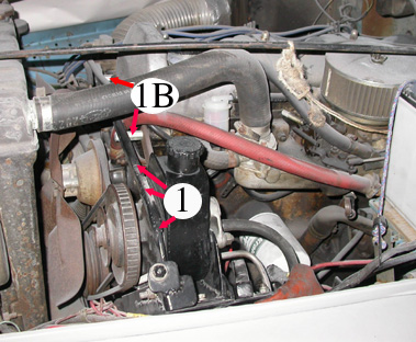
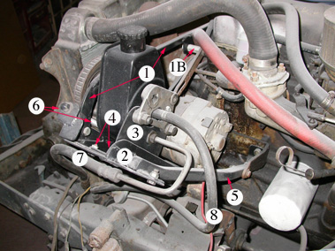
- Standard (GM) “can-o-ham” power steering pump was installed in fabricated brackets on the 230 Tornado engine. This was not easy! Luckily, the engine had a double pulley on the crank that allowed the pump to be turned with a 55″ Dayco #17550 belt
- Pump had to be mounted ‘high & outside’ the alternator which can’t be seen in this picture
- 1: pump saddle transverse support
- 1B: transverse support spacers which bolt through the timing chain cover to the cylinder head. These bolts must be inspected regularly for tightness.
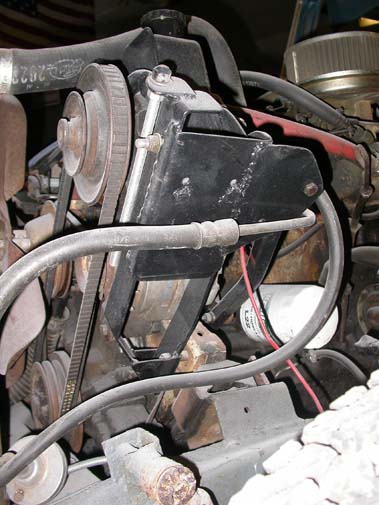
Another View of homemade pump bracketry – position of alternator can be seen.
- tranverse support & spacers(1B)
- fixed position saddle is supported in 3 places
- adjustable pump cradle (slides up & down in saddle to tighten belt)
- pump cradle securing bolts
- saddle fore/aft steady
- belt tension adjustment rod
- high pressure hose to steering box
- low pressure return hose (will get filter)
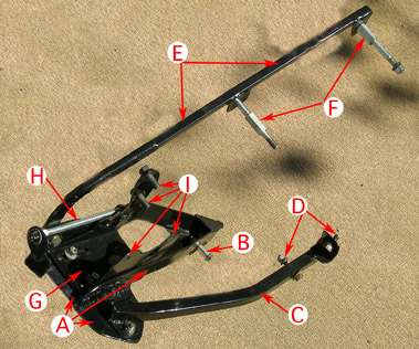
Fabricated pump bracketry design for the 230 engine
A is the fixed position pump bracket saddle, held in three places. 1st:fulcrum(B) of saddle base bolts to engine face plate.
2nd:square tubing (C) holds saddle fore & aft – attaches to the original unused rear generator mount at D. 3rd:side to side forces are controlled by a square tube transverse support(E) which is held to the engine front cover with two bolts & spacers(F)
The pump itself is attached to a sliding cradle(G) with 4 bolts(I). Threaded adjustment rod(H) controls belt tension by pulling cradle along saddle away from the engine
With the driver’s fender out of the way, here is a cat’s eye view of the bracketry.
Step Four
Where to root the steering shaft?
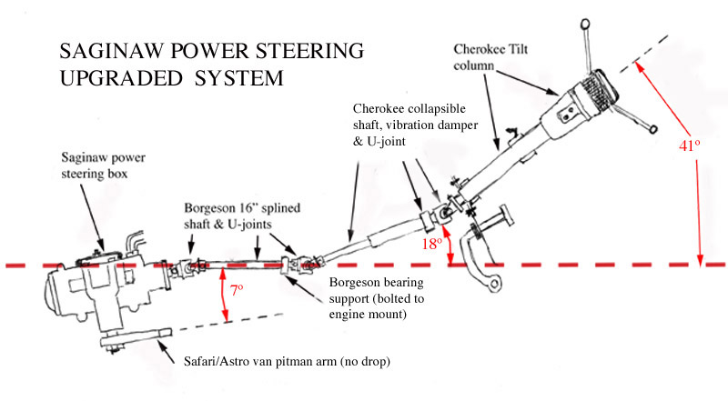
- Wooden stick (B) was used to determine the best angle and route for the new Borgeson/Cherokee steering shaft linkage. Three U-joints were required
- PTO shaft (A) will not be in the way of the new steering shaft but its support bracket (G) attaches to the engine mount (H) exactly where the steering will be routed. The PTO support must be moved.
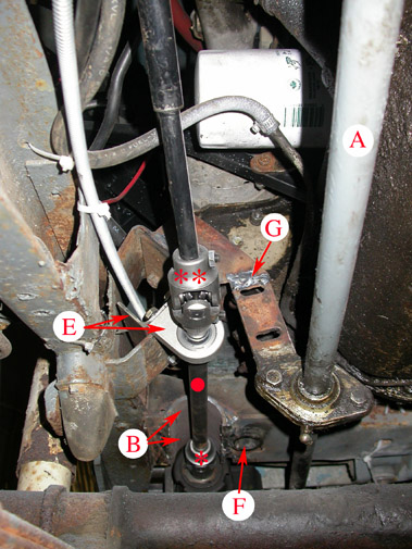
Steering column linkage. This view is forward from under brake/clutch pedals.
- New steering linkage uses two Borgeson U-joints (30/36* & 36/DD**), 16 inch double splined intermediate shaft(•) with bearing support(E), and Cherokee collapsible link with integral vibration damper(shown here disappearing at the top of the picture)
- Note: the Borgeson bearing support has no provision for greasing – without a Zerk fitting, this bearing will quickly rust and seize up. Keep it clean and lubricated once a year! If the bearing/shaft rusts, the symptom will be exactly like failure of the Saginaw power steering box. This is very misleading!
- B is a “Half pipe” (3″ diameter with 1/4″ wall thickness) welded into lower half of front X member can be seen at the bottom of the picture. The ‘cutout’ allows the intermediate shaft from the steering box to project under the cross member. This was the only cut and welding of the frame needed for the upgrade – unavoidable
- To the right of the “half pipe”, you can see the now disused hole(F) that the old Ross steering bell crank used to swivel on. Should, in future, some maniac want to change back to the OEM Ross steering, it can be easily done….
- G is the temporary support for the PTO shaft
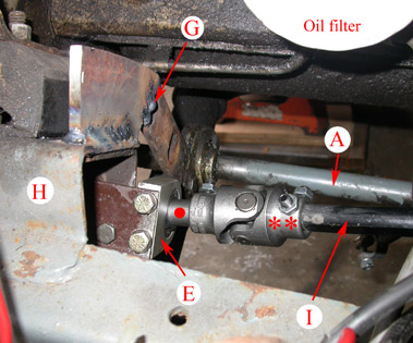
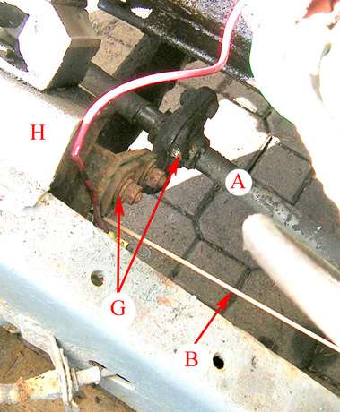
Another view of the Borgeson bearing support(E) attached to the engine mount(H).
- A is the PTO shaft. Its support had to be moved (temporarily welded at G to make room for the steering intermediate shaft
- I is the “double D” Cherokee collapsible shaft connected through a Borgeson 36/DD U-joint(**) to the 16″ Borgeson intermediate shaft(•)
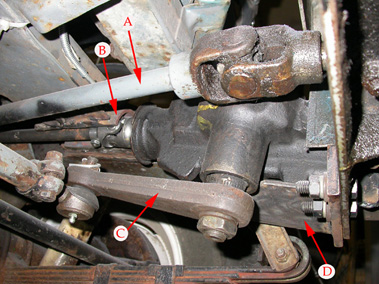
Under-front-bumper view showing Saginaw box and its vertical sector shaft
A: PTO winch shaft coming from the T case
B: “half-pipe” welded into the front X member (Borgeson 30/36 U-joint & 16″ double splined intermediate shaft running underneath)
C: Safari/Astro van straight Pitman arm is 6″ long (center to center) and moves the drag-link through a 7″ arc identical to the OEM Ross steering arc. This is exactly what we wanted.
D: steering box support plate gusset bolted to the winch cradle. This gusset makes the steering box attachment immensely stable – distributes the steering box twisting forces over both chassis rails.
Warning: any change to the factory design of your vehicle has potential dangers which could result in injury or death. Make sure any design changes or repairs are performed by competent, experienced technicians.
This content last updated: Sunday, April 11, 2010. Uploaded Dec 24, 2023.
