
Disclaimer and Warning: the following information on brake system modification is meant as an explanation of what we did, not as instructions for any work on any other vehicle. USE AT YOUR OWN RISK. Any brake system work done on any other vehicle should be carried out only by qualified brake technicians using the highest established standards of work and the best quality new parts.
The Willys wagon has a primitive OEM single action master cylinder under the floor boards. It is probably wise to install a more modern dual master cylinder which is safer and perhaps a “Hydroboost” power brake system that gets its power from a power steering pump. I decided to first install disc brakes/dual master cylinder and no Hydroboost to see if power brakes are even necessary. A Dana 44/Chevy disc brake conversion – with large calipers – was chosen after seeing the Jp article in the How to Modify Your Jeep Chassis and Suspension For Off-Road HP Book from the editors of Jp Magazine, chapter 33. The conversion will require wheel spacers or different wheels to clear the calipers, which might alter the character of the vehicle. Hmmm….
I was lucky enough to pick up a Chevy 3/4 ton hydroboost unit and a pair of almost new ’86 Chevy 1/2 ton calipers/pads and 21 inch long rubber flexible hoses for $20 privately but the brake caliper backing plates, which hold the calipers in place, had to come from a wrecker ($75). It was not easy to find an undamaged, non-rusted out set of backing plates from a 70s vintage Dana 44 front axle because most boneyards want to sell the complete axle to you. Nevertheless, the parts were coming together by the end of summer 2007 including the dual master cylinder and special bracket from ‘Herm the Overdrive Guy’ in Washington State. The ’86 calipers used metric hoses but were otherwise the same as late 70s models which I installed. NAPA took the ’86 calipers back as ‘cores’ for the older specification rebuilt calipers.
Master Cylinder
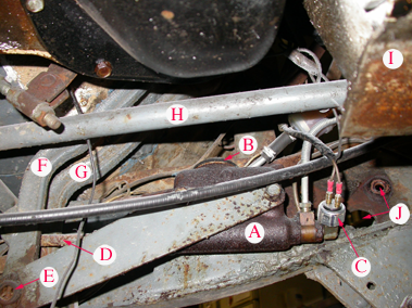
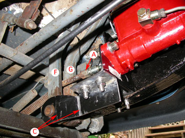
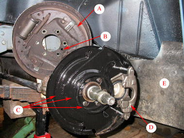
View of the primitive OEM factory sub-floor braking system.
A: OEM Wagner Master Cylinder
B: Brake fluid access lid (almost impossible to get to without an access hatch)
C: Pressure brake-light switch
D: adjustable brake pedal plunger
E: Fulcrum for brake and clutch pedals (the bearings on the shaft become worn out after 40+ years)
F: Sub-floor brake pedal lever
G: Sub-floor clutch pedal lever
H: PTO shaft
I: Engine sump protective skid plate
J: Chassis holes for original factory Ross steering box (now replaced with Saginaw power steering)
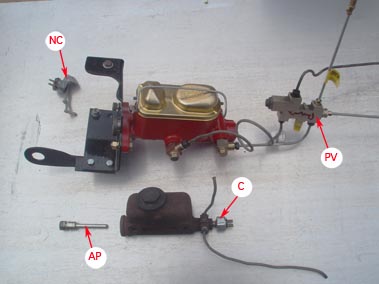
New master cylinder vs old
- The new dual master cylinder and special bracket were obtained from ‘Herm the Overdrive Guy’. I also got the ‘banjo bolt’ set up from Herm so that the brake lines would come off the master cylinder at a tight angle.
- A Combination (metering/ proportioning/brake failure) valve(PV) came from a 1990 Jeep TJ that had front discs and rear drums.
- The original master cylinder activating plunger(AP) was used with the new system.
- Finally, the old pressure brake light switch(C) was deemed too much fuss to hook up to the new system, so a mechanical switch(NC) was ordered from ‘Watson’s Street Works’. This adjustable switch is controlled by the subfloor brake pedal lever.
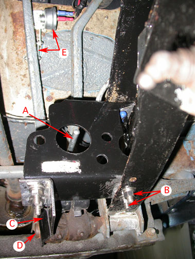
New dual master cylinder bracket in place after the welded original chassis support for the OEM MC is removed with a cutting wheel.
- ‘Herm the Overdrive’s’ dual master cylinder bracket must be located accurately so the brake pedal plunger(A) is centralized as shown.
- A strengthening ‘arm'(C) locates the bracket on the brake/clutch fulcrum tube(D).
- the bracket is bolted to the lower chassis with two 5/16″ bolts(B)
- a mechanical brake light switch with its adjustable activating arm(E) hooks up to the stock wiring. This switch comes from Watson’s Street Works.
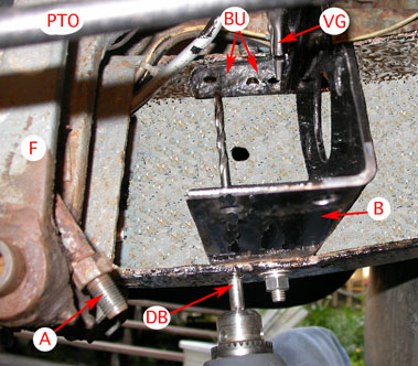
Drilling the upper chassis support holes is awkward
- A is the brake pedal plunger with its adjustable extension removed. Brake pedal F
- B is Herm’s bracket with one lower bolt in place
the bracket upper(BU) flange is held against the upper chassis with needlenose visegrips(VG) so that holes can be accurately drilled. One way to drill the upper holes is with a long bit (DB) inserted through the lower holes one at a time. This bit is a Boeing surplus unit.
Master cylinder bolted to the secured bracket
- position of the bracket determines how the adjustable brake pedal plunger(A) engages the MC piston
- the locating ‘arm’ that holds the inboard side of Herm’s bracket is secured with two bolts. I had to add a pair of bends(C) I also used 5/16″ bolts instead of the 1/4″ ones that came with the kit.
- F & G are the brake and clutch pedals
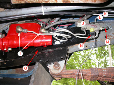
Master cylinder hook up to the Jeep TJ Combination Valve(J) – will the proportioning be OK?
- I are the optional ‘banjo fittings’ Herm offers so that the brake pipes can come off the MC at a tight angle
- K=brake pipe to rear axle
- L&M=brake pipes to RF and LF disc brakes
- N is the brake circuit failure switch with its wiring dangling
- O is the small remnant of the removed old MC support bracket. A protective cover plate could be attached here
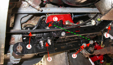
Protective skidplate is cobbled together out of shelving steel – this is light duty protection… It also reinforces and strengthens the Master cylinder bracket
- A is the hand cable to the T- case brake drum
- Skidplate bolts to the bottom of Herm’s bracket at B (hidden in this picture); inboard MC bolt(C); stock spring hanger holes(D) and stock frame holes up front (E)
- A hidden diagonal rod(green line) gives great rigidity to the master cylinder – no movement was seen even under max pedal pressure
Front Brakes
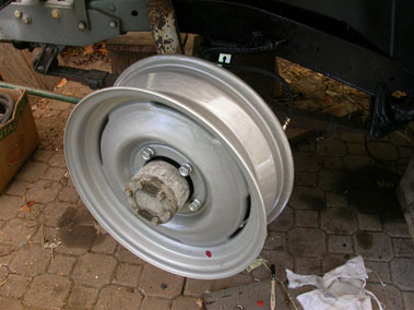
OEM 11″ drum brakes – although others might disagree, I found that the performance was inadequate.
- Factory brakes were completely rebuilt with new components (including brake lines) in 1997. Very little improvement was experienced. Some family members felt they were not strong enough to stop vehicle safely!
- Stopping distance from 50mph was measured at an outrageously long 195 feet (n=6)
- driver’s side front drum has been machined beyond maximum tolerance
- note Cutlass locking hubs
Old and new brake backing-plates
- OEM 11″ brake backing-plate (A) has a strange extra hole (B). Willys used the same backing plates for front and back axles – the extra hole is for grease overflow from the rear axle bearings.
- C: ’70s GM/Dana 44 style disc backing-plate is made up of 3 pieces spot-welded together – thin splash guard; heavy stamped part that holds the caliper & dished ring that seems to protect the bearings
- D: Chevy single piston caliper
- E: Heavy weight custom oversize mudguard really protects the underside of the Willys.
Knuckle modification
- To make room for the caliper the rear flange area of the knuckle is ground away (F) between the two rear most bolts using an angle grinder. This work is best done with the caliper bracket in place allowing you to repeatedly test fit the caliper
- For caliper clearance, the cast iron plug (for grease) must be replaced with a flush plug. The simplest replacement is a 1/2″ electrical box plug (G). A small amount of the caliper casting (facing the knuckle) also needs to be ground off allowing clearance near the new grease plug
- The six grade 5 bolts (H) must be replaced with slightly longer (1 1/4 inch) grade 8s. Check the six knuckle threads carefully to see if they are worn or stripped. If they are damaged, you will have to install studs from the back in some of the positions. Not all six can be installed as some will foul the axle U-joint inside.
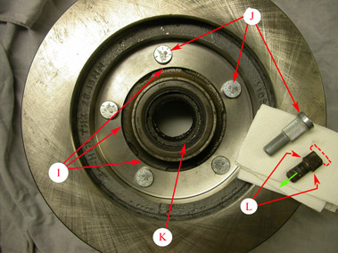
Now the tricky part…the rotor must fit perfectly on the old hub once the drum has been removed.
- The rotor inner hole must be machined so that it fits tightly onto the inner flange shoulder of the old hub inside(I). I found ‘Randy’ who did the machining accurately
- J: Dorman studs have longer splines which allow for the thicker rotor. The new studs are driven through the rotor holes and tightly into the old hub. The Dorman stud splines are not actually tight in the rotor holes, only in the hub
- K: old seal must be replaced and inner bearing washed and regreased
- If you look closely at the old lugstud (L), you can see that it was swaged at the factory. Swaging involves deforming the edge of the splines into the drum face making the drum and hub one piece. Because of the swaged/enlarged splines, the stud cannot be driven out as expected – instead, the head is cut off (dotted line) and the stud is driven out the other way (green arrow).
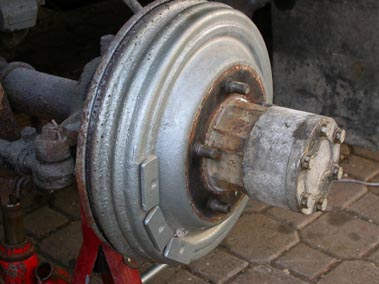
Disc brake converted front hub ready to go.
- At last, the disc brakes are installed and only need a final cleaning before use. How much better will stopping power be?
- note 1-1/4″ thick SpiderTrax wheel spacer that allows use of original Willys wheels.
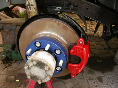
Willys wheel over Chevy disc brakes.
- With SpiderTrax spacer, there is ample clearance between the wheel rim and the disc brake caliper.
I suspect a spacer of 3/4″ would have been enough but SpiderTrax doesn’t offer that thickness. Track is increased 2-1/2″ with the spacers. This increased track makes the wheels stick out too far.
An other way to deal with the caliper to wheel clearance but maintain near factory track would be to find a set of 16″ wheels with a different inside profile, greater offset and 5 on 5-1/2″ bolt pattern. 1999-2004 Suzuki Vitara/Chevy Tracker steel wheels have the same bolt pattern, same center hole and at 6-1/2″ wide, might fit. I will look for a set. Lastly, you could change the caliper backplate and rotor spacing as shown at: <http://groups.yahoo.com/group/WillysTech/photos/album/1940009696/pic/list> this is obviously the best but most complicated solution to the problem.
Rear Brakes
The rear drum brakes on the Dana 44 axle are fairly primitive. There are two types: ones with parking brake mechanisms and ones without. The latter style should always have a parking/emergency brake drum on the back of the D18 Transfer Case. It should be noted that if the vehicle has that transmission style brake, it is dangerous to jack one rear wheel of the vehicle up and still expect the parking brake to work! It can come as a major shock to realize that lifting one rear wheel (doggie style, so to speak) means a total loss of the parking brake function.
With stock brakes. the pair of shoe adjusters, on the backplates at 3 and 9 o’clock, need manual adjustment regularly. Adjustment requires that the ‘cam’ inside the adjuster pushes outwards against the upper part of the brake shoes – see photos below…
Many Willys wagon and pickup owners upgrade the rear drums with self adjusting (self-energizing) “Bendix” innards, while others have gone the full disc brake route. It is likely, but not guaranteed, that vehicles with disc brakes at all 4 corners, will also need a different master cylinder and power brake booster.
I kept the rear drums and simply cleaned them up as follows:
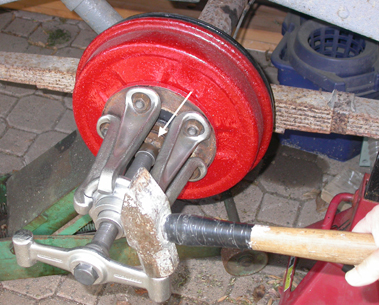
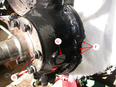
First, the rear hub with integral drum must be removed. A good quality hub puller like this Hazet unit makes short work of the job.
I received this tool on my 19th birthday many decades ago and it has pulled hubs that other cheaper units could not…
The white arrow shows the castellated nut has been loosened off about 1/8″ but is still in place on the axle threads – this way the hub doesn’t fly off and, of course, land on your foot.
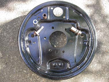
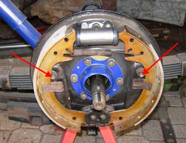
Here is the back plate lovingly cleaned and painted with Por15.
Note the two shoe adjusters (eccentric cam to push the shoes outward against the drum), washers and long nuts.
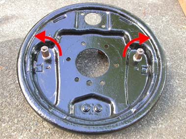
Again, here is the outside of the backing plate with the shoe adjusters loosely in place. I used NeverSeez on the moving surfaces and threads of the adjusters.
The adjusters are twisted in opposite directions so that the little eccentric cams push against the upper part of the shoes… Once the shoes are snug against the drums, but not tight, the long 9/16″ nuts are tightened.
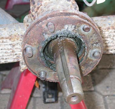
This is what the axle flange that the backing plate bolts to looks like after 45 years of use. I carefully cleaned off the hardened grease and applied a light emery paper sanding.
This is a good time to check that the key fits properly into the axle keyway – any burrs are removed.
Clean the taper that will receive the hub carefully, removing any rust – clean the hub internal face too. I applied some light oil and then completely wiped it off. Some people recommend smearing the taper with NeverSeez but I do not, worrying that this compound will allow the hub to twist back and forth on the axle taper. This could lead to failure over time. It is better, IMO, to have a direct contact between hub and axle taper.
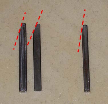
Here are Dana 44 axle keys.
On the left, is the correct key for our Wagon axle (1/4″ wide and about 3/8″ tall)
On the right, is the correct key for the heavier version of the Dana 44 axle that came with Forward Control Willys trucks (about 1/4″ wide and tall)
Our wagon was incorrectly equipped with one of each of the above keys!
Also, note that the angle at the top of the keys is different – on the left about 20 degrees on the right, about 12 degrees.
To make matters even more annoying, the middle key is a replacement, made “off-shore”, which has a 22 degree top angle. This new key can’t be used at all because it is exactly 1/4″ wide (instead of 0.247″) and therefore is too wide to fit in the axle keyway!!! Bugger!
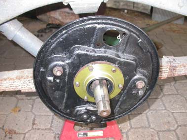
Now the backing plate can go back into place and a new grease seal can be installed. Crown Automotive Products makes these nice replacement seals in the USA – and they are cheap at $7.
Can you see the assembly mistake? Here the right rear backing plate is attached to the left rear position – therefore the entire mechanism is at an angle. The error is easy to fix at this point…
Time to save up for new suspension springs and shocks!
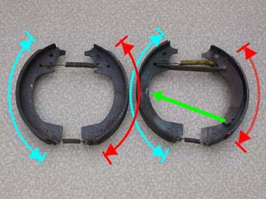
A word about brake shoe modifications here… The set on the left is somewhat incorrect .
On the left are the old shoes from our vehicle (’65 wagon). Note that the friction area is the same on the ‘Leading’ (blue) and ‘Trailing’ (red) shoes. Wrong. One of the shoes, the ‘Trailing‘ shoe, should have less friction material. Many brake shops install shoes with the same friction material in the Leading and Trailing positions insisting it makes no difference – others disagree.
On the right is a pair of shoes from rear brakes with integral parking/emergency brake – note the lever and transverse rod at the top just under the yellow spring. The lever is attached to the shorter/Trailing shoe – it is correct. The green arrow shows how the brake cable would pull.
Correct shoes in the correct positions. See March 2011 below****
Note the ‘Trailing’ shoe has less friction material and our rear brakes have no integral parking/emergency brake components. The front of the vehicle is to the left.
The red arrows show the little eccentric cams, when adjusted later, will push outward high up on the shoes. If the adjusters are turned the wrong way, they will still push on the shoes, but at a lower point.
I cleaned out the slave cylinders and lightly sanded their 1 inch bores with #400 emery paper. New US made rebuild kits including rubber seals and internal springs etc.($8 each) are again cheap and very worthwhile.
New suspension springs and shocks in place!
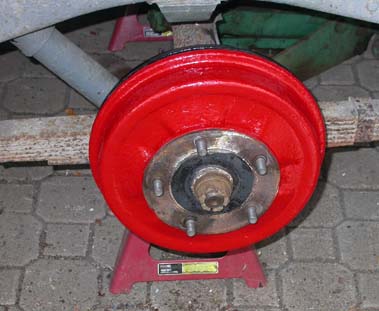
At last, the drum and hub are back in place. Next, slide in the axle key and install the washer and big castellated nut. Do not install the hub with the key already in place or you might crack the hub!
Tighten the big nut to over 150lbs (one shop I trust recommended 200 lbs) once the wheel is back on and insert a new cotter (split) pin of the correct size.
Smear some grease over the nut/washer/hub assembly before installing the protective cap. The grease will hopefully keep water from getting into the hub/axle taper from the outside.
Lastly adjust the shoes outwards using those manual adjusters so the shoes make a slight, but not tight fit with the drums. Make sure the wheel can turn but not freely.
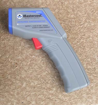
After a short test drive, touch the wheels with your fingers to make sure they are not too hot. If you can arrange it (Fathers’ Day, B’day or Christmas), get an Infrared Thermometer – this is the inexpensive Mastercool 52224-A. This makes testing the temperature of the drums very fast and accurate.
If the hub/wheel area around the lugnuts is hot, not warm, loosen off the brake shoe adjusters a little. In any case, readjust the shoes after a few days of driving.
Everything should be Roses.
BRAKE FUNCTION
SUCCESS (“Known knowns”***) The updated brake system works. During the first drive, even before the pads were ‘bedded in’, it was obvious the vehicle stops much better than before!
TROUBLE (“Known unknowns”***): With the new updated brake system bled multiple times (old fashioned two-man style and MityVac style), a brake pedal “sponginess” and seeming long pedal-travel are still spoiling proper operation. After extensive discussion on the WillysTech forum and other forums, the following list of possible reasons was assembled. The long/spongy pedal could be caused by:
- Rear brakes not adjusted ‘snug but not tight’ against the drums
- Old flexlines, front or back (or both) are too old – the flex lines are bulging under pressure
- Calipers installed upside down (left caliper on right side and vice versa). This makes bleeding of the calipers almost impossible
- Air still in lines due to the shape of steel line bends or configuration of the flex lines
- brake pedal plunger is adjusted too long which then never allows the MC piston to fully move back to resting position
- New MC bracket is flexing under pedal pressure
- Master cylinder is defective
- Master cylinder is incompatible with calipers (bore diameter is too small- 1-1/16″ vs 1-1/8″)
- Elevation of master cylinder compared to the caliper. If the master cylinder is lower than the calipers, there can be a slight vacuum effect when the brake pedal is released. This vacuum pulls the caliper pistons back. The 2 lb residual valve should control this problem.
- The calipers are not touching the rotor at the correct angle due to damaged backing plate
- Bearings are not adjusted correctly (loose) allowing the rotor to move outward or inward during braking
- Incorrect design of calipers – there are two caliper designs: the first keeps the pads touching the rotor and the second pulls the pads back slightly when the brake pedal is released. Each caliper design requires a MC that works with that design. Perhaps the calipers and MC are not compatible
- The ratio of brake pedal movement is incorrect for the necessary MC piston travel. This means that even though you push the pedal almost to the floor, the MC piston isn’t pushed in quite enough. This is not easy to change as the Willys pedals do not have multiple ‘push rod’ attachment points as a ’39 Plymouth does! <www.jalopyjournal.com/forum/showthread.php?t=291107&showall=1>
- The TJ Combination Valve is mounted upside down which could trap air or cause some other problem
- The TJ Combination Valve is incompatible with the new MC – the MC has a residual valve already installed and the Combo Valve also has a residual valve. Residual valve redundancy may be problematic.
- BIGGER TROUBLE: Unknown unknowns***………….
*** acknowledgement to Donald Rumsfeld for his descriptive analysis and wit.
October 2008:
The rear brakes, front bearings and brake pedal plunger are correctly adjusted; the two front flex lines are new; the MC bracket has been reinforced so that there is absolutely no flexing movement; the MC lines were test plugged resulting in a rock hard pedal and the front pads are checked for proper alignment with no twisting when brake pressure is applied.
This leaves only three likely possibilities: either there is air trapped somehow somewhere in the lines or the Combination Valve is causing the problem, or the master cylinder’s bore and piston are 1/16″ too small.
I will rebleed the lines using a Motive Pressure Bleeder Kit and if that doesn’t solve the problem, be forced to replace the Combination Valve with an in-line adjustable proportioning valve from Wilwood or SSBC.
Against the somewhat ridiculing comments from one well known WillysTecher, I predict pressure bleeding will solve (or at least substantially decrease) the problem….
November 15, 2008: My prediction seems to have been gloriously wrong!
- the system was rebled using the Motive Pressure Bleeder – only a small bubble was eliminated – no real improvement.
- the TJ Combination Valve was removed and the brake pipes replumbed withoutit. The system was rebled – again, there was very little if any improvement.
I must measure the distance the pedal plunger moves into the master cylinder – will it be over an inch and enough? One post on a hot rod forum known as The H.A.M.B., suggested that the vehicle should be driven for a while and the sponginess would disappear. This doesn’t sound logical but I’m stumped anyway….
January, 2009: As soon as the ‘great snows of 2008’ abate, I will try out some of the techiques recommended by Bill Williams (Diagnosing Spongy Brake Pedals)
August, 2010: The chronic ‘Spongy Brake Problem’ has become legendary on the WillysTech Forum but has still not been solved.
The rear brake cylinders were rebuilt, backing plates thoroughly cleaned and new brake shoes and rear brakeline flexible hose installed. No improvement. The next step is to replace a bent brake line and then to cap off the two brake cylinders on the rear axle to see if that removes the symptom…
March, 2011 **** Leading vs Trailing brake shoe friction surfaces. Mistake discovered!
A brief explanation of the difference between Bendix drum brakes and Lockheed/Ford design as I now understand it.
Bendix brake shoes have more friction material on the Trailing shoe, while older design Willys/Lockheed (originally designed by Henry Ford) shoes are set up with more friction material on the Leading shoe. I assembled our rear Willys brakes using information from several internet sites and a phone conversation with a local brake shop. I got the wrong information!
Henry Ford’s design has a fixed/immovable pivot at the bottom of the brake shoes and an expanding ‘slave cylinder’ at the top of the backing plate. Willys Overland used this design up to some of the J series Wagoneer/Gladiator pickup days.
Bendix designed so-called “self energizing” brakes and registered an exclusive patent. These drum brakes have a loose assembly at the bottom of the backing plate which allows the shoes to rotate a bit which increases the pressure on the drum. There is usually a ‘star adjuster’ at the bottom between the lower shoes. The net improvement is lower pedal effort and more even wear.
Now the story goes, Henry, being the kind of guy who didn’t want to pay unnecessary royalties to Bendix for their superior design, refused to put the better brakes an any of his models except Lincolns. Henry’s behaviour was completely consistent with his refusal to use the vastly superior Robertson (square head) screws over Philips – again to avoid royalties. Then there’s the story of Henry setting all his factory yard rail track in solid concrete instead of wooden ties…. But we are digressing…
Warning: any change to the factory design of your vehicle has potential dangers which could result in injury or death. Make sure any design changes or repairs are performed by competent, experienced technicians.
This content last updated: Sunday, May 29, 2011. Uploaded Dec 24, 2023.
