
WARNING AND DISCLAIMER: The following description is simply to show how we were involved in replacing the wiring in a built-in-1928 house, not as any advice on the replacement, design, installation or maintenance of any other electrical system. USE AT YOUR OWN RISK! The installation of replacement wiring (with all required governmental and utility permits) of any electric equipment or system must only be carried out by trained, qualified and certified electricians. Only CSA/ULc approved wire and fixtures can be used while strictly adhering to electrical codes.
Background.
Our house was built in 1928 and consequently has “Knob and Tube” wiring in the original structure. An addition was built in 1990 which, of course, has modern “Romex” wiring. The original distribution box was updated to a ‘SquareD’ QO Load Center circuit breaker type which became a subpanel to a new larger box. By 2012, we were hearing rumours that more and more insurance underwriters were requiring the replacement of obsolete “Knob and Tube” systems before policies would be renewed, so it was obvious that an electrical up-date, that up to a few years ago was on the horizon, was approaching fast.
At the same time, we knew there was some “vermiculite” insulation in the attic which contained <1% asbestos and that any house being torn down would have to have the asbestos removed first. The value of the property therefore was linked partly to any asbestos contamination during demolition. In other words, once again as with many problems in life, we could pay now or pay later. So, we decided to have the asbestos-contaminated insulation removed, do an attic rewiring and then re-insulate to a much higher level than existed in the house previously. By chance, there was a rebate from Fortis (our local natural gas utility) which we could enjoy if the new insulation work was completed by a specific date.
The cost of a complete house rewire by a contractor was quite high, perhaps $15k or more. This price was too high for us but we could afford a budget of $10k for the entire enterprise including attic asbestos abatement, rewiring and attic reinsulation (with treated cellulose) to R40. Could we keep to our budget? To achieve this relatively thrifty goal we would supply ‘sweat equity’ which we have experienced numerous times in the past.
Here is what is involved in rewiring the top floor of a three bedroom house by accessing the attic. The main floor would be rewired from the basement as the second phase of the Knob and Tube replacement job. Once the job was finished, our electrician would supply us with a certificate attesting to the rewiring which we could present to our insurance agent when we renewed our house policy.
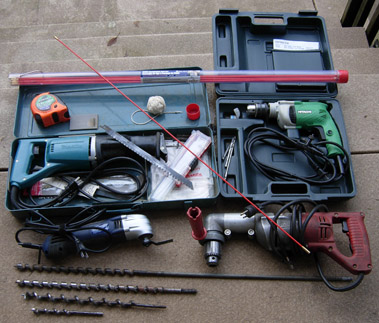
Tools needed for rewiring an old house.
Tools needed to bore holes and fish new electrical lines through the walls of an old house are shown. Note 1/2″ drills including an old Milwaukee geared down “right angle” unit with a selection of augers.
Near lower left, a wonderful cheap “oscillating tool” that will make very thin cuts in tight places and at the top, a set of 10 one meter long fiberglass rods to fish down through holes. String and tape measure are needed. A reciprocating jigsaw will make quick cuts in almost any wall (you’ll need six long wood/metal cutting bimetal combination blades)
Not shown are electrical tape; masking tape to mark out where holes are to be cut and a special extra long (54″) bendable 9/16″ Greenlee Flex drillbit wood auger 090354B. This auger can use a special Klein handle (Flexbit placement tool 53715 SEN) that allows one to hold the bent auger as you drill.
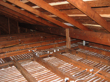
Attic with the old insulation removed.
You can see the lath and plaster ceilings over the hall and bedrooms with the porcelain Knobs and Tubes still in serviceable condition (no mold or rodent damage could be found – the original wiring was still flexible and in excellent condition).
It is interesting that all three bedrooms, original bathroom and hallway lights/switches were served by one (1) circuit.
Each bedroom had only two (2) plugs in the baseboards. Note the single white new wire (new circuit) at lower right, that was installed years ago so that our daughter could plug in a small space heater without ‘blowing a fuse’.
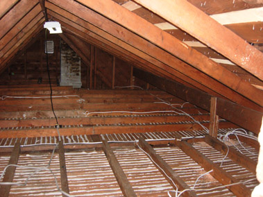
Here is the attic during new Romex wire installation and with much of the old wiring removed. Holes were drilled down into the wall plates allowing for new lines to be routed to new switches and wall plugs.
The plugs were mounted one foot up from the floors, not in the baseboards. Ceiling lights were rewired and the boxes sealed against airflow.
Note the fluorescent fixture (one of two), that I suspended at the peak of the attic, so there would be adequate light to do the work. Also, not shown, are a few pieces of plywood used to protect my knees.
All remaining Knob and Tube wire-ends were carefully taped off – it isn’t possible to remove all ghost wires from inside the walls unless many holes are made in the lath and plaster. Since these inaccessible wires are disconnected, they are inert and can remain in situ.
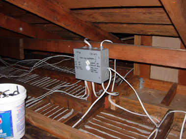
Our electrician ran the new lines up to the attic and into this large distribution box. The wires have not been fully fastened down in this picture but the box has been labelled carefully.
The new circuits are supplied through Arc fault Circuit Interruptor (AFCI) circuit breakers which now are required by most electrical codes for bedrooms.
Since there was so much manual labour required to physically bore holes and run the wires, we did most of it and only had our electrician do the connections. This saved 90% of the costs, I suspect.
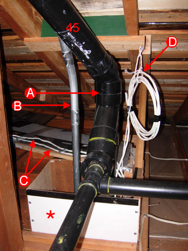
Few older houses have an easy access from the basement to the attic but in our case the ‘soil stack’ runs in a 12″ by 14″ empty column up from floor to floor to the attic. Here you can see that I built a simple wooden box (*) around the mouth of the opening to the attic so insulation will not fall down the hole.
A is the soil stack that is joined by two bathroom plumbing vents. Note the 45 degree bend (45) in the stack as it runs along the underside of the roof to vent at a higher location – this is to allow for a solar panel at that spot.
B is the 1″ diameter EMT (metal electrical conduit) for wires from our roof-surface solar panels to the basement.
C are the two new 14/2 Romex lines for the 3 bedrooms, hallway and original bathroom.
D is an extra 14/3 line that will allow additional circuits if needed in future. A thin nylon rope is also in place to pull up other cables should they be needed in future.
There is a cablevision line also which cannot be seen in this picture while the monitored smoke detector line is routed elsewhere.
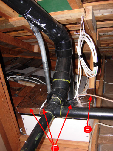
Here is the 3-part cap that covers the mouth to the column (F). This should slow or stop any air movement/heat loss. I made this out of styrofoam-covered in aluminum duct tape.
The cable vision line can be seen here at E
I installed ‘gyproc’ bulkheads at the basement ceiling and mainfloor ceiling levels to act as vertical fire breaks.
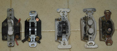
Here is a selection of the old wall switches you might encounter. The quality of these old units is remarkable and all but one are still serviceable.
What you will note is how positive the switching action is – they make a gratifying click as they engage or disengage…
I’m sure someone on this planet would love to have these antiques – my price would be reasonable.
Wall Switch Box Removal.
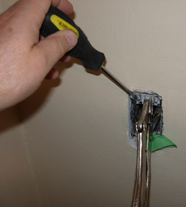
The original wall switch boxes are held in place by upper and lower pairs of nails into little brackets screwed to the box. Of course these nails have been plastered over.
In order to do the least amount of damage to the walls, I used visegrip pliers to bend down the upper edge (and bend up the lower edge) of the boxes. This reveals two screws that hold the little securing brackets.
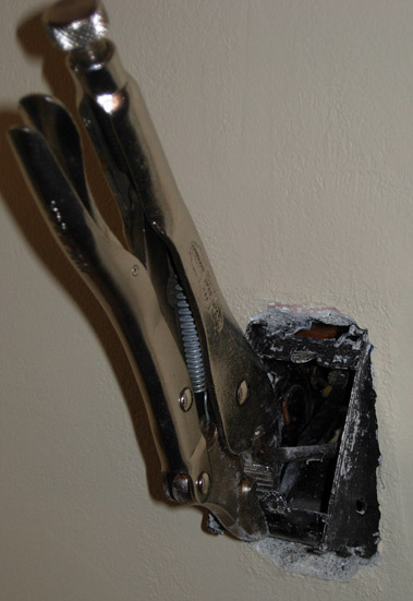
With the screws removed, it is easy to lever out the old box while you push the old wires back through the box ports.
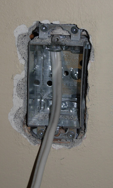
With the old box out, it is straight forward to remove just enough plaster to gain access to the nailed-in brackets that held the old box.
With care and practice, one gets pretty quick at this job. In most cases I was able to replace the box with a new one so that no patching of the plaster was required.
Of course if the box is in an exterior wall, patching and careful sealing against drafts is always required.
Note the old wire that has been carefully taped off so that no bare copper is evident – I always installed a marrette/wirenut first and then electrical tape. Even though these old wires are no longer ‘live’, you don’t want any possibility of them touching any new live wires.
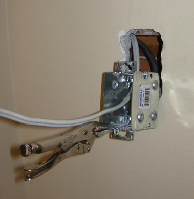
Here’s a new switch box affixed with 4 screws in the exact same place where the old box came out. I was a bit crude with the extraction and there is unnecessary wall damage, particularly on the left side and bottom in this case… obviously I was impatient, probably late for dinner.
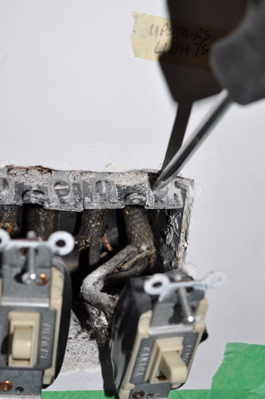
I found double box removal and replacement to be much more difficult. These double boxes controlled the hall lights at the bottom and top of the stairs – they have additonal wiring for the “three-way” switches.
Again, you can see the bracket-securing screws at the top of the paired boxes. I have bent down the tops of the two boxes for access.
Note, someone replaced the switches with newer ones at least 25 years ago.
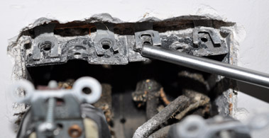
And now the brackets can be separated from the boxes – I simply bend the little tabs up and out of the way.
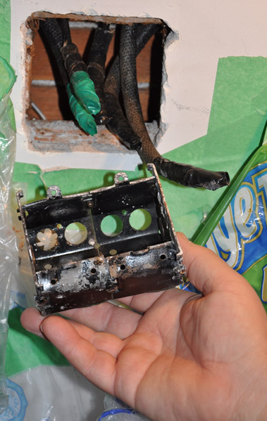
In this shot you can see the old double box – note that in the left-most wire aperture/port, the brass gripper, designed to hold the wire cover which protects the old wire, is still in place.
Note also the cleaned-up plaster around the shiplap backer to which the boxes attach. It was pleasing to see that the old holes line up with the new boxes – somethings, thank heavens, do not change in 86 years!
The old disconnected “ghost” wires remain in the walls and so, I taped them carefully before pushing them in and sideways out of the way.
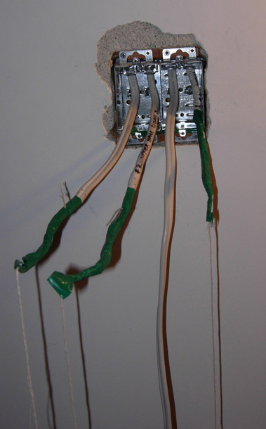
New Double box installation.
This turned out to be tricky because, with 4 wires (two 14/2 and two 14/3) entering the top of the double box, there wasn’t enough clearance to lever the boxes into place. You can see I damaged the plaster buggering around during the first futile attempts.
Solution:
1…attach string to each wire,
2…loosen off the wire securing clamps inside the boxes,
3…pull the wires up into the attic until their ends were inside the wall,
4… feed the strings through their respective holes in the boxes,
5… work the paired boxes into the wall,
6…gently pull the strings and then wires, one by one back into the boxes, while pushing the wires down from the attic. Note: Fine needle-nose pliers really help.
7… retighten the box securing clamps,
8… have a beer.
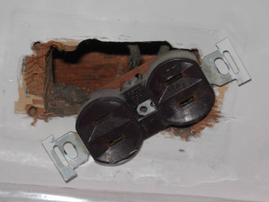
Here you can see a wall receptacle in the baseboard – not an original but still of the old non-ground design. This may represent the worst part of the Knob and Tube wiring design because there is no metal box. .
Of course, these old receptacles were removed, the disconnected wires carefully taped up and the baseboard holes covered and painted
The number of new wall “plugs” was increased at least three fold in each room. They were mounted 12″ up in the walls.
This page last updated: Sunday, January 25, 2015. Uploaded Dec 24, 2023.
